Peek Design Group is made up of a very unique combination of very talented folks with a wide range of skills. When we designed the renovation of 637 Polk Street, I knew that one of the challenges would be to find someone who could create the detailed house-parts needed to give it that true ‘Craftsman’ look. I didn’t have to look far to find one of our key folks, Dave Lawrence, who has a love for woodworking and access to a wonderful shop that was ideal for the construction of these pieces.
So for this and the next blog, I’ve asked Dave to share some of the details of the process he took to shape these timber elements.
Here’s Dave . . .
Bargeboards
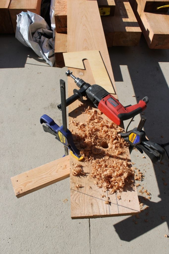
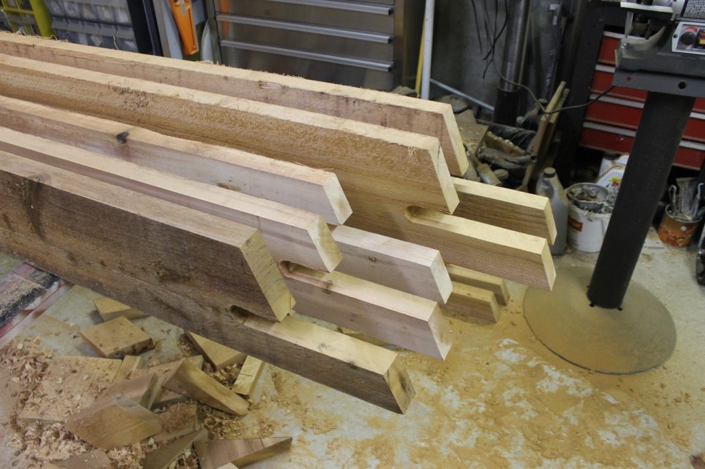
There were a dozen 2×10 and 2×8 Bargeboards that needed to be shaped from full dimension Western Red Cedar. A template was created from the architectural drawings by printing full scale and cutting the template from ¼ plywood. The first step to shape the end of the barge boards was to bore a 1” diameter smooth side hole using a Forstner bit and the template for positioning. A board was clamped to the under side to prevent tear-out.
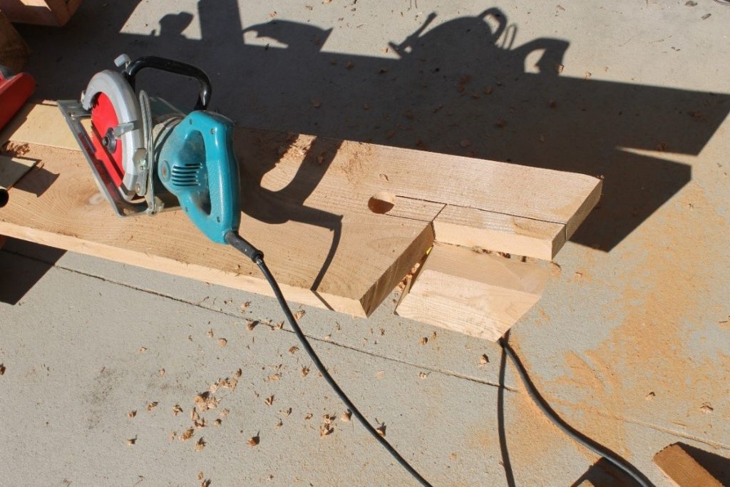
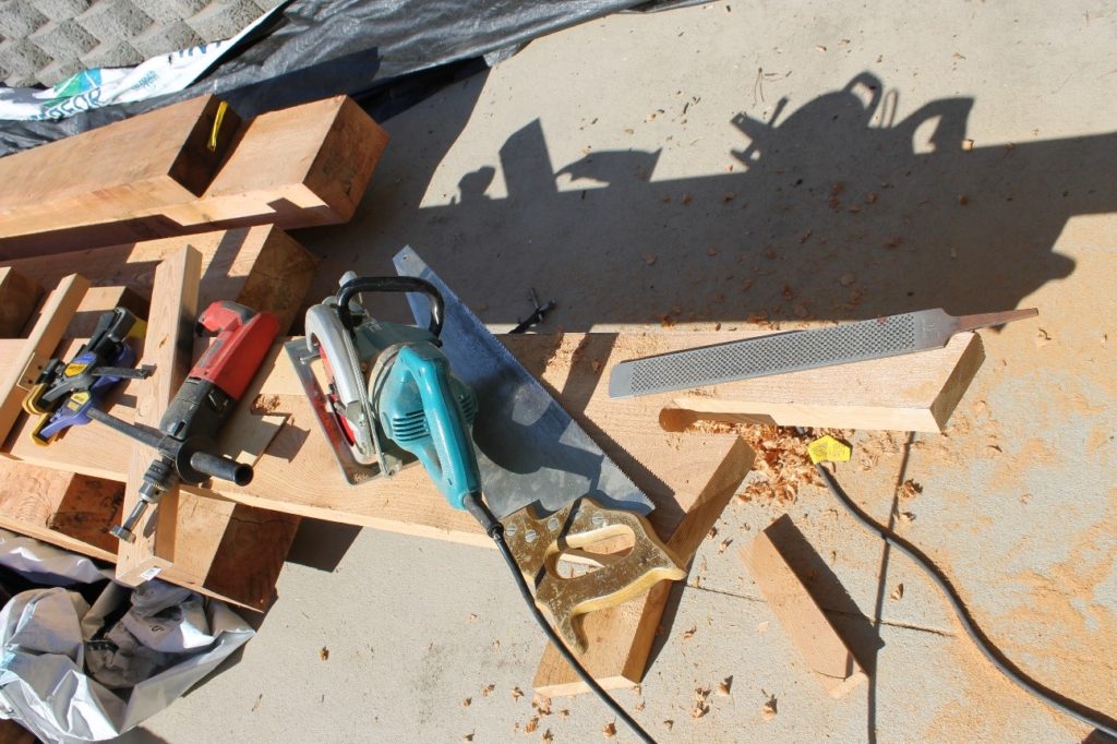
The next step consisted of a series of four straight cuts – two for the ends at the vertical angle of the roof pitch and two cuts to “approach” the 1” hole. The skill saw could not make a complete cut without intruding into the face of the barge board. The remainder was cut the old fashioned way – with a hand saw. The “throat” of the barge board detail was then trued up with a wood rasp.
The last step was to sand the rough-sawn sides and edges of the timbers smooth and seal the exposure portion of the ends with an epoxy product before priming all surfaces.
Bargeboard Brackets
The Brackets were made from three components of full dimension Western Red Cedar; a 2×6 backer, a 6×6 chamfered beam and a 4×8” curved brace. We first chopped the 6×6 beams due to the set up needed on the chop saw and the size of the timbers. The square cut was accomplished with two cuts on opposing faces of the 6×6.
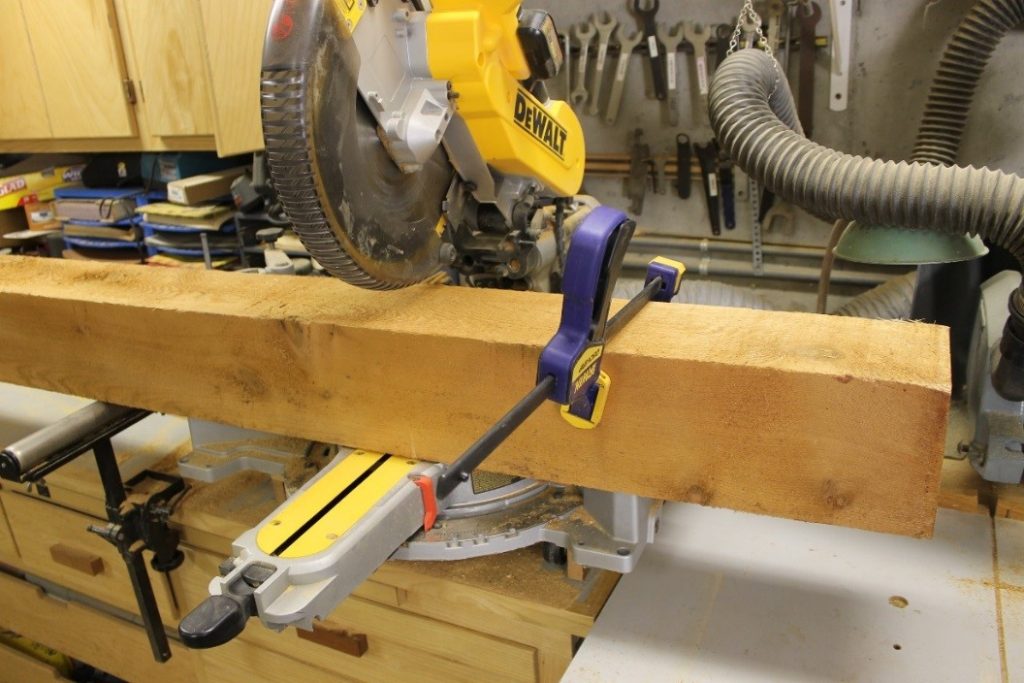
Then it is was just a mater of chamfering one end of the beam at 1” on all four edges. A stop was set up in order to insure that the chamfers coincided with each other on all four faces. They were set aside and allowed to dry out at this stage.
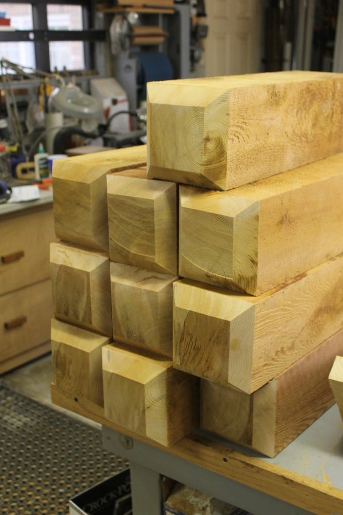
The chamfers were then sealed with epoxy to protect the exposed end from the elements.
The next step was to shape the curved braces from the 4×8 stock.
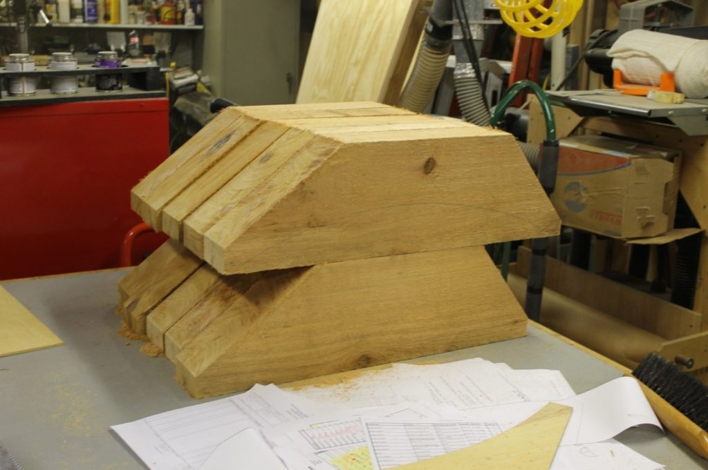
We created a template from full scale architectural drawings and then chopped the 4×8 timbers into sections determining the best cut in order to cull out any large knots or checks in the wood. The braces were then chopped on the mounting faces to make sure it formed the critical 90 degree angle.
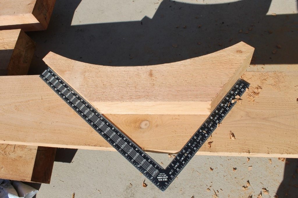
Then it was on to the band saw to cut the curve.
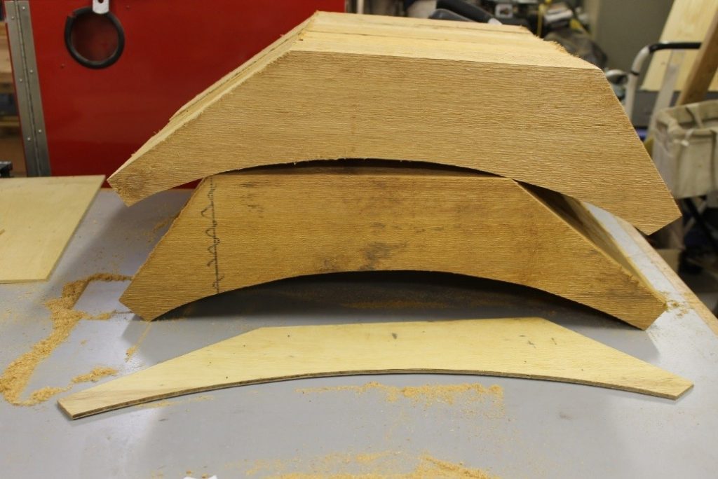
The sides and curves were then sanded smooth with 80 grit sandpaper.
The following picture shows the pieces cut from the 4×8 stock.
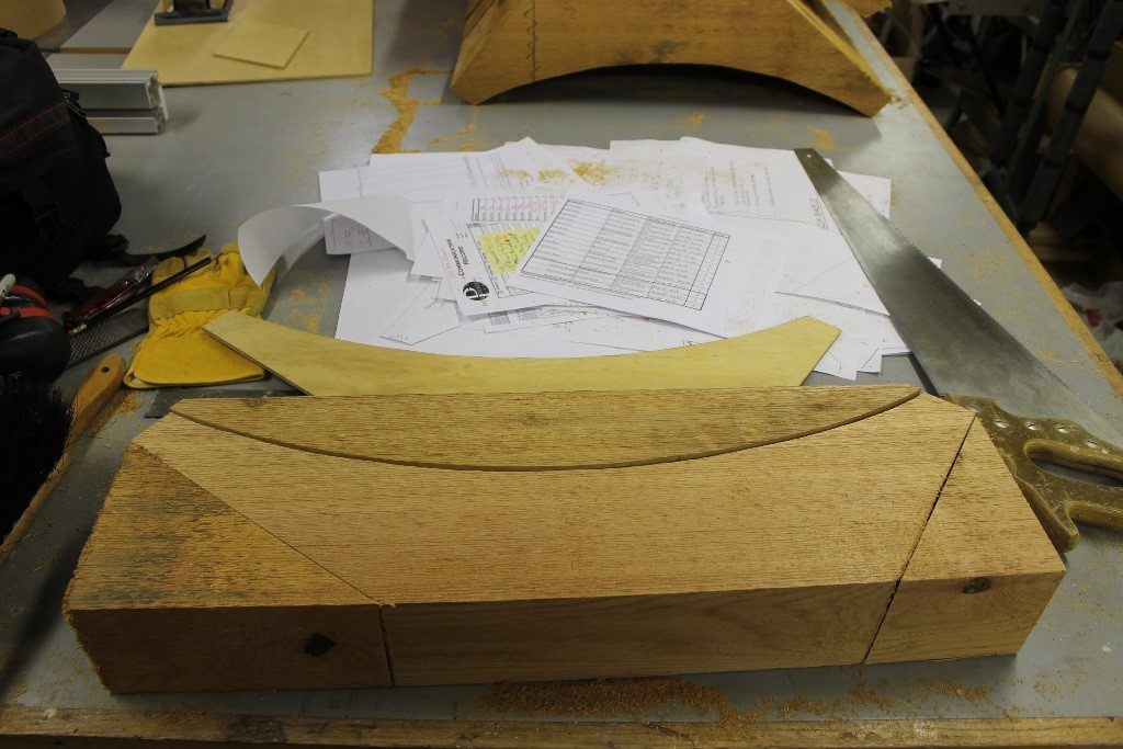
We then bored a pair of 1” diameter holes in each end from the curved face. This allowed us to drive a pair of 1” diameter oak dowels to anchor the braces to the 6×6 beam and the 2×6 backer.
One of the scraps from cutting the curve is used to create the boring “template” to guide the Forstner bit at the same position and angle.
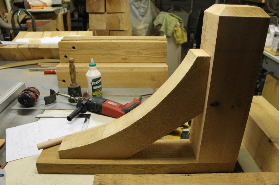
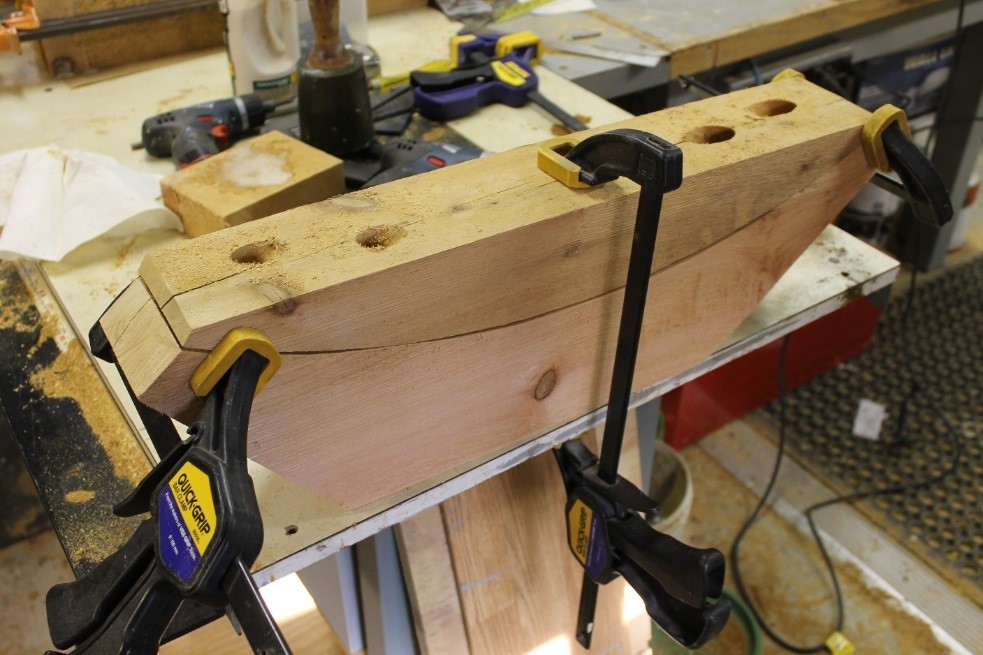
Dry fit of the three components after smoothing the surfaces.
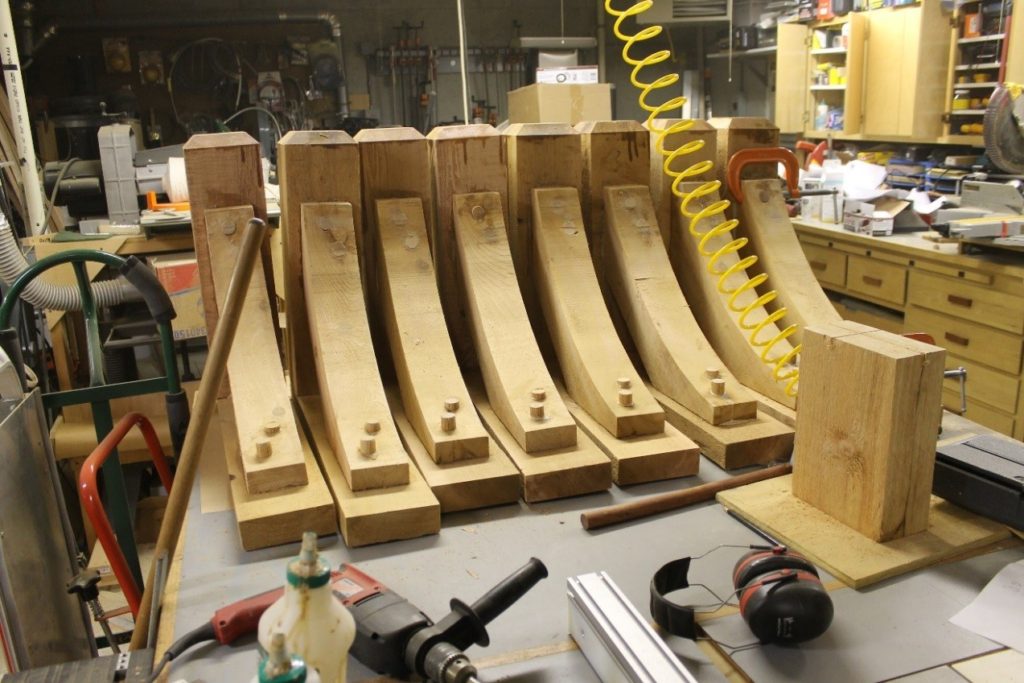
Eight of the ten brackets with 1” dowels driven and glued with water proof adhesive into the 6×6 beam and the 2×6 backer.
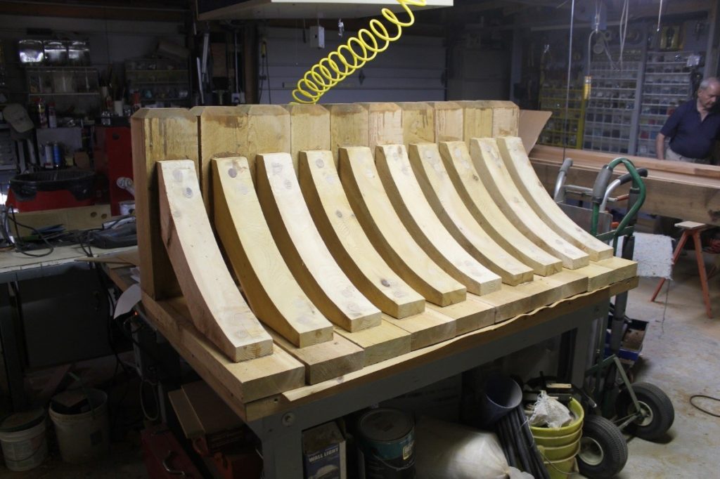
The ten brackets with the pegs cut, chiseled flush and sanded smooth. The chamfered ends that would be exposed were then sealed with epoxy. The completed brackets were then given a coat of primer after everything was cured.

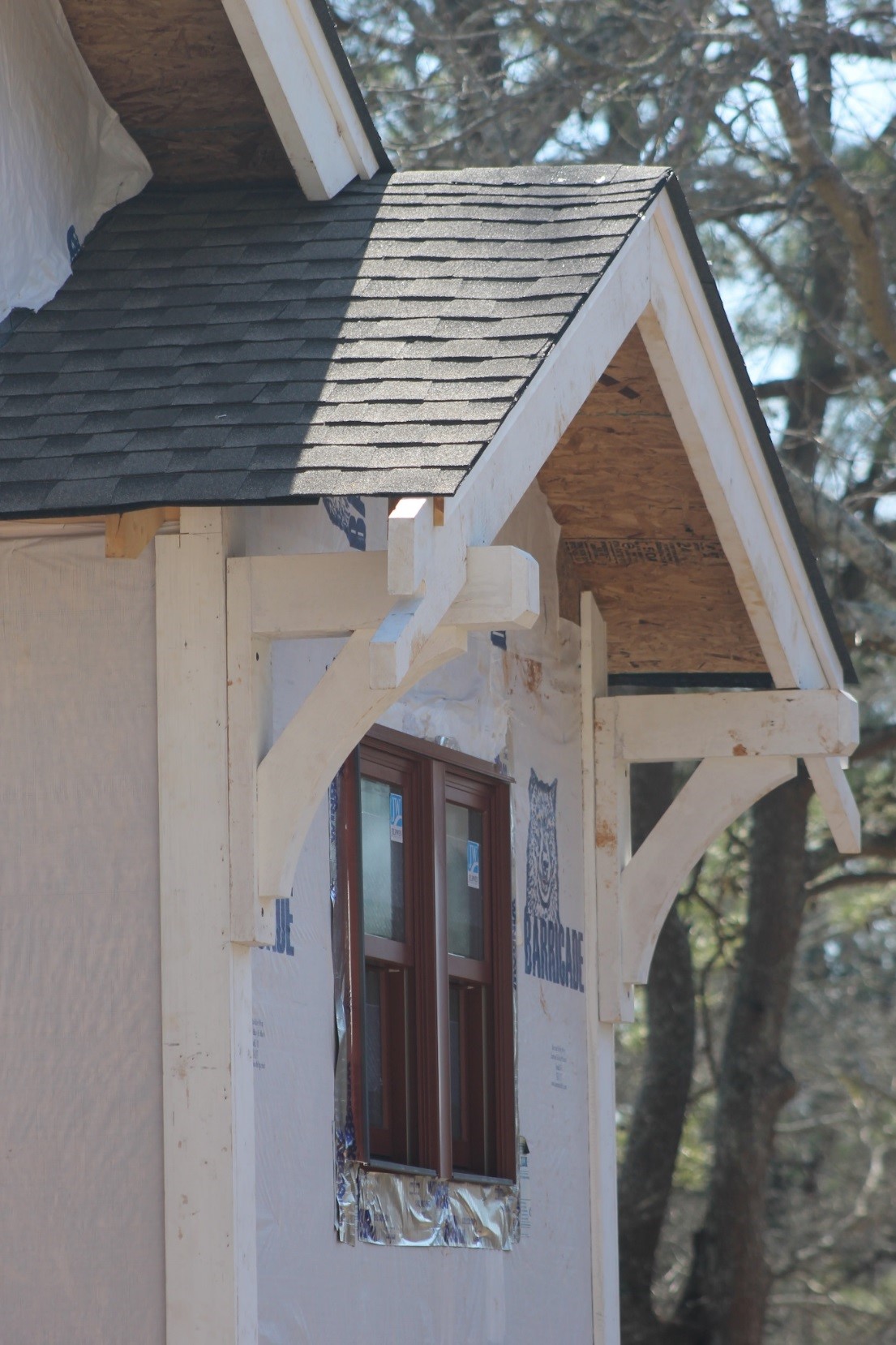
A pair of completed and primed brackets installed and supporting the barge boards.